On this page
- Why continuous dissolved oxygen readings matter in an aeration tank
- Installing a wastewater dissolved oxygen sensor at a representative point
- Check flow requirements before choosing the sensing principle
- Optical or polarographic: what should you compare?
- Commission the sensor and verify the measurement
- Routine inspection and troubleshooting checklist
- Make the trend useful to operations
- Frequently asked questions
Key takeaways
- Choose a measurement point that represents the tank zone operators need to monitor, and keep it accessible for inspection.
- Check local water movement before selecting a polarographic sensor. The WSDO4051 lists a minimum flow rate of 2.5 cm/s.
- The DSMD1900 optical sensor does not consume oxygen and has no minimum-flow requirement stated on its product page.
- Verify calibration, temperature compensation, units and signal scaling during commissioning, then record a baseline.
- Set cleaning and verification routines for site conditions and sensor instructions rather than using a universal interval.
A wastewater dissolved oxygen sensor is useful when its reading represents the part of the aeration tank operators need to understand. Location, water movement at the sensing surface, fouling and verification checks all affect whether the trend can be trusted.
Before choosing a sensor, define the process zone the measurement should represent. Then check the sensing principle against the conditions at the proposed location. Commission the instrument to its instructions, record a baseline and plan inspections around site conditions rather than assuming a fixed interval will suit every tank.
Why continuous dissolved oxygen readings matter in an aeration tank
A continuous DO trend shows how the measured dissolved oxygen changes over time at the sensor location. Operators can use the record to see whether conditions are steady, changing or behaving differently from an established pattern. The U.S. Environmental Protection Agency describes continuous monitoring as a way to assess changes in DO throughout the day in its dissolved oxygen factsheet.
A spot measurement answers a narrower question: what was the reading at that time and place? A continuous instrument can show changes between manual checks, but it does not explain why a change occurred. A shifted trend could reflect process conditions, fouling, a change in water movement at the sensor or an instrument issue. Treat the reading as evidence to investigate, not a diagnosis on its own.
There is no universal operating target to select from a sensor specification. Setpoints and control responses depend on the plant and treatment process. Agree what the measurement is intended to support, who reviews it and what checks are needed before changing process settings. When planning online water-quality monitoring and integration, consider how the DO reading will be displayed, recorded and used alongside other plant measurements.
Installing a wastewater dissolved oxygen sensor at a representative point
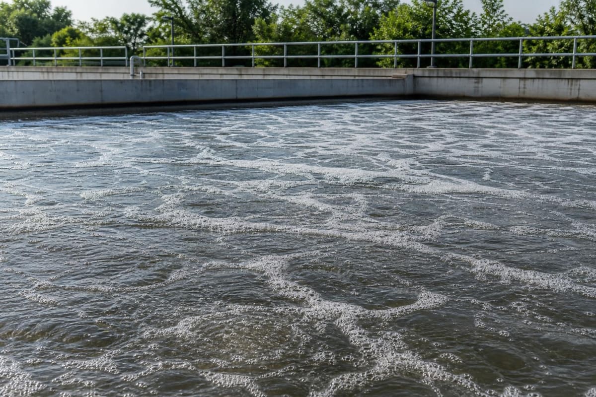
Choose the measurement point according to the process question. If operators need to follow a particular zone, position the sensor so its reading represents that zone. Do not assume one point describes the whole tank. Mixing and water conditions can vary across an aeration tank, and a measurement from one location may not describe every area.
Walk the proposed location under normal operating conditions. Consider whether water movement at the sensor suits the selected principle, whether the sensing face will remain exposed to the process and whether deposits or other material could collect around it. Inspection, cleaning and removal should be practical. A position that is hard to reach can make a routine task easy to delay or skip.
Consider how the installation behaves as the plant operates. Aeration, mixing patterns and water levels may change. A point that seems representative in one operating state may not remain so in another. Observe the location during normal operation and discuss unusual or uneven flow patterns with the process team. If the measurement is intended to support a specific operating decision, make sure the point actually relates to that decision.
The mounting arrangement must suit the selected sensor and tank. Check insertion depth, orientation, clearance and the method of securing the sensor against the current installation instructions. Do not infer a mounting method from a product photograph or from the fact that another sensor fits a similar tank. The water and wastewater applications served by LKS Group involve different process and installation conditions, so check the proposed position against the site layout.
Access matters after installation, not just during commissioning. Before fixing the position, consider how a technician will inspect the sensing area, remove the sensor and return it to service. Check that the mounting does not obstruct the sensing face or make cleaning awkward. Confirm that cables can be routed and secured as the sensor instructions require, and that the arrangement allows the instrument to be identified in maintenance records.
Check flow requirements before choosing the sensing principle
Flow at the sensing element matters particularly for a polarographic sensor. This principle consumes oxygen at the sensing surface. If water movement is too low, oxygen at that surface may not represent the surrounding water reliably. The U.S. Geological Survey describes polarographic membrane-type sensors as sensitive to water velocity and notes fouling from algal growth and sedimentation in its guidance on dissolved oxygen measurement.
The WSDO4051 polarographic wastewater DO sensor is one example. Its product information specifies a minimum flow rate of 2.5 cm/s and describes a stainless-steel grit mesh membrane. Check that the installed position can provide the stated movement at the sensing face. Do not assume general circulation in the tank is enough. If the local flow condition is uncertain, check the sensor instructions and review the location with the site team before relying on the reading.
An optical sensor measures by luminescence and does not consume oxygen at the sensing surface. The DSMD1900 optical DO sensor has no minimum-flow or agitation requirement stated on its product page. That difference can matter where water movement is limited. It does not remove the need to choose a representative, inspectable position. Fouling, deposits or a poorly chosen measurement point can still make the trend less useful.
Do not select a principle on flow requirements alone. Confirm conditions for the specific instrument, including the flow at the sensor, mounting, access and the effect of the surrounding process. A stated absence of minimum-flow requirements does not mean that every location will provide a representative measurement.
Optical or polarographic: what should you compare?
Compare the designs against the job the sensor must do, rather than treating either principle as universally better. The DSMD1900 uses optical luminescence. Its product page lists a 0 to 20 mg/L DO range, automatic temperature compensation, RS485 Modbus RTU output and no membrane to replace. It can report DO in mg/L, ppm or percent saturation. The listed calibration methods include air calibration and zero-oxygen calibration.
The WSDO4051 uses a polarographic electrode. Its product page lists a 0 to 20 mg/L range, accuracy better than ±0.1 mg/L and a stainless-steel mesh membrane. It has a stated minimum flow requirement of 2.5 cm/s. Temperature-compensation element options include PT100 and PT1000. The listed standard cable length is 5 m, with other lengths available on request. Confirm the selected configuration before specifying the cable or compensation input.
The operational differences are worth making explicit. The optical design does not consume oxygen at the sensing surface and has no membrane replacement task listed. The polarographic design depends on water movement at the sensing surface and includes a membrane in its measurement arrangement. Both still need a suitable location, inspection and measurement checks. The maintenance work at a particular site depends on the wastewater and installation, not just the sensing principle.
Compare the signal and mechanical interfaces as well. Confirm that the intended transmitter or control system accepts the sensor output and protocol, and that power, cable length, temperature compensation and mounting suit the installation. A shared DO range does not make two sensors interchangeable. The product pages describe different outputs and configurations, so verify the complete signal path before procurement. LKS can help review the sensor options and water-quality monitoring arrangement, but selection still needs to be checked against the plant’s required inputs and installation details.
A useful selection discussion includes the measurement point, local water movement, cleaning access and the receiving system. Record which sensor configuration has been selected and what needs to be checked at commissioning. That gives the installation and operations teams a clear basis for verifying the instrument when it arrives on site.
Commission the sensor and verify the measurement
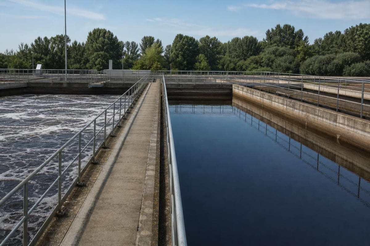
Commissioning should establish a baseline that later checks can be compared with. Follow the procedure for the selected sensor, including its stated preparation, calibration and stabilisation steps. Do not transfer a calibration procedure from one sensing principle to another. The DSMD1900 product information lists air and zero-oxygen calibration methods. Use the relevant sensor instructions to determine how to perform them.
Check that temperature compensation is configured as intended. The DSMD1900 lists automatic temperature compensation, while the WSDO4051 uses selectable temperature-compensation element options. Confirm that the installed configuration and receiving instrument agree. A sensor reading can be represented incorrectly if the input configuration or signal scaling is wrong.
Verify the displayed value and signal path before handing the measurement to operations. Confirm that the value appears in the intended unit, that the trend is recording and that any alarms or control responses associated with the point are understood. Check the full connection to the intended transmitter or control system. Do not assume compatibility from the sensor type or range alone.
Record the commissioning condition, method and result in the plant’s measurement records. Note the sensor configuration and any relevant settings so that later checks can be compared with a known baseline. A dated record helps distinguish gradual drift from a sudden change after cleaning, maintenance or a process event. The guidance on calibration checks and keeping measurement records can support consistent recordkeeping.
Routine inspection and troubleshooting checklist
Set an inspection and verification routine according to site conditions and the sensor instructions. Do not apply a universal cleaning or calibration interval. Wastewater conditions vary, and fouling can affect the usefulness of a continuous measurement. U.S. Geological Survey guidance covers inspection, cleaning, calibration checks and documentation as parts of continuous-monitor maintenance in its monitor maintenance report.
During inspection, look for deposits, visible fouling, physical damage and changes to the mounting. Check that the sensing face remains exposed as intended and that the conditions around it have not changed. For a polarographic sensor, inspect the membrane and confirm that the required water movement is still available at the installed position. For an optical sensor, inspect the sensing area and follow its specific cleaning instructions. Use only a cleaning method suitable for the selected sensor.
When a reading seems questionable, compare the trend with recent maintenance records and process observations. Look for implausible flatlining, an abrupt shift or a persistent difference from an independent check. If practical, record the reading before cleaning. Clean according to the instructions, then record the result and carry out the applicable verification or calibration check. This sequence helps show whether the change followed maintenance, rather than leaving only a new value with no explanation.
A difference from an independent check needs investigation, not an automatic adjustment. Confirm that the check relates to the same process conditions and measurement area, then review the sensor’s calibration status and configuration. If the two measurements remain inconsistent, document the discrepancy and involve the instrumentation and process teams. Avoid changing aeration or control settings simply to make an unexpected sensor value look normal.
Before making a process change, check the measurement point, flow at the sensing element, fouling, calibration status, temperature compensation and signal scaling. If the reading remains doubtful, record what has been checked and what still needs investigation. A clear maintenance history is more useful than repeated adjustments without a confirmed cause.
Make the trend useful to operations
Agree how operators should interpret and respond to the measurement. Define which process zone the sensor represents, who reviews the trend and what checks are needed before changing a control response. This prevents a local reading from being treated as a whole-tank condition without evidence.
Keep the trend connected to maintenance information. Record sensor cleaning, calibration or verification, configuration changes, mounting changes and independent comparisons. When a trend changes, these records can help establish whether it shifted after a process event or an instrument intervention. If the measurement is integrated into a control system, confirm the signal path and display scaling during commissioning and after relevant changes.
Review the measurement point with operations and maintenance when the tank layout or operating pattern changes. Reconsider whether the sensor still represents the intended zone and whether access and flow conditions remain suitable. A continuous signal is valuable when its meaning is understood and its reliability is checked, not simply because it is available on a screen.
Frequently asked questions
Does a wastewater DO sensor need water flow past it?
It depends on the sensing principle and model. The WSDO4051 polarographic sensor lists a minimum flow rate of 2.5 cm/s. The DSMD1900 optical sensor has no minimum-flow or agitation requirement stated on its product page. Check the selected sensor’s instructions and the actual installation conditions.
How often should an online DO sensor be cleaned or checked?
There is no universal interval. Set the routine according to wastewater conditions, observed fouling, sensor instructions and plant verification practice. Record inspections and checks so the interval can be reviewed against the instrument’s condition at the site.
Can I compare readings from optical and polarographic sensors directly?
Compare readings only after confirming that they use compatible units and that each is installed where it can represent the intended process zone. Check calibration, temperature compensation and measurement locations. Investigate a difference rather than assuming it is a process change.
Should I use mg/L or percent saturation for plant monitoring?
Choose the unit that fits the plant’s monitoring and reporting purpose, then use it consistently in displays and records. The DSMD1900 lists mg/L, ppm and percent saturation. Confirm the selected unit and scaling in the receiving system.
For help reviewing a sensor principle, mounting point or signal interface against your application, contact our engineers.

LKS Engineering TeamEngineers at LKS Group, supplying and servicing instrumentation, valves and monitoring systems in Malaysia since 1998.