On this page
- Why 4-20 mA loop surge protection is still needed
- Trace the complete loop before choosing a protector
- Match the protector to the signal and normal operating voltage
- Decide where protection belongs in the installation
- Grounding and bonding: check the discharge path
- Practical selection and commissioning checklist
- Frequently asked questions
Key takeaways
- Map the transmitter, supply, cable, interfaces and receiving input before selecting a protector.
- Check rated and continuous operating voltage separately against the actual loop.
- Compare discharge-current ratings as documented, not by the headline figure alone.
- Follow the protector’s wiring and grounding instructions, and keep shield design distinct.
- Decide on protection at one or both ends from the cable route and site design.
A 4-20 mA loop can still be damaged or interrupted by transient overvoltage. The signal’s normal behaviour does not protect the cable or connected electronics. Effective 4-20 mA loop surge protection depends on matching the protector to the circuit and providing a suitable path for transient current to the site grounding and bonding system.
Start by tracing the complete loop, from its power source and transmitter to the receiving input. Mark the interfaces and exposed cable sections, then compare the circuit requirements with the protector’s ratings and wiring instructions. A voltage version that sounds close to the loop rating is not enough to establish suitability.
Why 4-20 mA loop surge protection is still needed
A current loop’s normal signal robustness does not make its cable and connected electronics immune to transient overvoltage. Long or exposed field wiring can couple transient energy into a transmitter, input circuit or interface. Possible sources include direct lightning effects, induced transients and other electrical disturbances. Damage can occur even if a strike is not on the instrument itself.
The Federal Highway Administration’s handbook discussion of lightning damage to outdoor electronics identifies direct strokes, power surges, induced transient voltage spikes and capacitive voltages as possible causes. Its traffic-signal example also describes induced currents in signal cables. That example illustrates a possible coupling mechanism, not a required layout for a process plant.
A protector is intended to limit transient voltage at connected equipment and provide a route for surge current to be diverted. It cannot promise immunity from every lightning event. IEC 61643-21:2025 covers surge protective devices connected to telecommunications and signalling networks, including protection against direct and indirect lightning effects and other transient overvoltages. It describes devices that use at least one voltage-limiting component to limit surge voltages and divert surge currents. The standard’s scope provides context; it does not replace checking the selected device against the actual circuit and site design.
Trace the complete loop before choosing a protector
Draw the circuit from the transmitter to the receiving input and back through the loop supply. Mark the transmitter, power source, field cable, junction boxes, barriers or isolators where present, and the control-system input. Record whether it is a two-wire loop or another arrangement, and identify any equipment powered by the loop. These details affect what the protector must be compatible with.
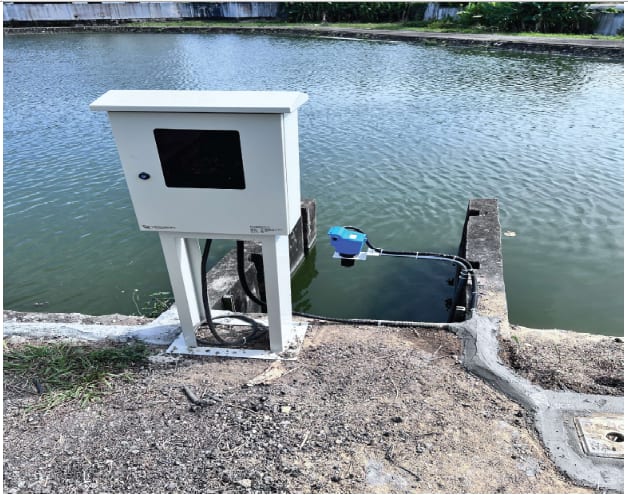
Then mark the cable route. Note sections that run outdoors, between buildings, or between equipment with separate earth references. Identify where the cable enters a cabinet or enclosure and where it connects at the field end. This route map helps the team review possible transient entry points and the equipment exposed along the path.
Do not map only the signal pair. List other conductors and interfaces that enter or leave the equipment, including power, communications, shields and bonding connections. A transient may reach equipment by a path other than the 4-20 mA pair. If a barrier, isolator or shared interface is in the circuit, check its own connection requirements. Do not assume that a signal protector covers every connected path.
For example, a flow installation may have a field transmitter and receiving instrumentation separated by a long cable route. When reviewing flow systems and their field instrumentation, consider how the field device connects to the control system. The explanation of how an electromagnetic flow meter measures flow may help identify the instrument in a process loop, but the protector still has to suit the actual circuit and cable route.
Match the protector to the signal and normal operating voltage
Do not select a protector from the 4-20 mA signal range alone. Check the loop supply, transmitter requirements, input circuit, wiring arrangement and any interface devices. The voltage available to the instruments must remain suitable when the circuit is assembled. Compare the circuit’s normal voltage with the exact protector model’s continuous operating rating, and check the device documentation for its intended application.
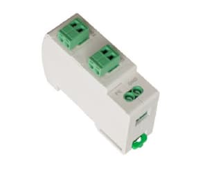
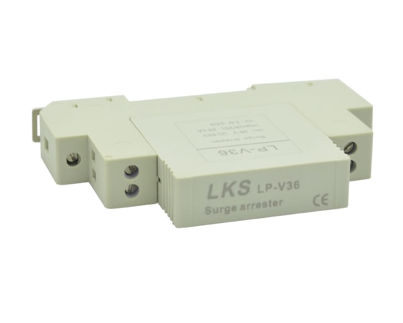
The LKS LP-V signal-line protector for two-wire instrument loops is described for automation and process-control instrument loops, including two-wire current-loop instruments. The LP-V series has rated working-voltage versions of 5, 12, 24 and 36 V. Its stated maximum continuous voltages are 8, 18, 36 and 54 V respectively. The product page lists protection levels below 50 V for the 5 V and 12 V versions, and below 80 V for the 24 V and 36 V versions. It also gives a maximum discharge current of 20 kA (8/20 µs) and insertion loss of no more than 0.3 dB.
The LKS LP-C/TER signal protector for 4-20 mA and twisted-pair data lines is listed for 4-20 mA control loops and RS232, RS422 and RS485 twisted-pair data lines. Its rated operating-voltage versions are 5, 12, 24 and 48 V, with stated maximum continuous operating voltages of 8, 18, 30 and 60 V. For the 5 V, 12 V and 24 V versions, the stated protection level is below 80 V line to line and below 100 V line to ground. For the 48 V version, it is below 150 V line to line and below 200 V line to ground. The product page gives a nominal discharge current of 5 kA (8/20 µs), line to line and line to ground, and insertion loss of no more than 0.5 dB.
Keep the ratings distinct when comparing devices. The rated operating voltage identifies the product version. The maximum continuous operating voltage states the continuous voltage limit given for that model. The protection level describes the voltage associated with the device’s limiting behaviour under its specified test conditions. These values answer different questions, so do not treat them as interchangeable.
Insertion loss is another signal-path characteristic to review. The LP-V and LP-C/TER pages state different insertion-loss figures. Consider those figures alongside the circuit and receiving equipment requirements; insertion loss alone does not prove that a protector will suit a particular loop. Check any other signal-path characteristics specified for the exact model.
Do not choose by a headline discharge-current figure alone. The LP-V page states a maximum discharge current, while the LP-C/TER page states a nominal discharge current. Those labels are not interchangeable. Compare the ratings as documented, including their test conditions, and consider the operating voltage, protection level, signal-path requirements and application guidance together.

Decide where protection belongs in the installation
Assess the exposed cable entry points and the equipment at both ends of a field run. Depending on the route, site layout and protection design, a protector may be needed near a transmitter, at a cabinet entry, or at both locations. Do not assume that every loop needs protection at both ends, or that one device at one end is always sufficient.
Consider what equipment the protection design is intended to protect and where a transient could enter the circuit. A long outdoor route may present different exposure from a short cable within one equipment area. Equipment at each end may also have different connections to earth. Resolve these questions against the project design rather than applying a universal placement rule.
Follow the protector’s marked line and equipment sides and its wiring instructions. Check that each signal conductor passes through the intended terminals and that the grounding connection is made as specified. If the documentation does not make orientation or terminal assignments clear, confirm them before energising the loop. A correctly rated protector connected outside the intended signal path may not provide the intended protection.
Grounding and bonding: check the discharge path
A signal-line protector needs an effective connection to the site grounding and bonding system so transient current has a route away from connected equipment. Do not assume that a device installed in the signal path will provide effective protection if its required earth connection is missing. Check the specified terminal, conductor, connection method and route against the product instructions and project design.
The LP-V product page specifies earth-link resistance below 5 Ω for effective protection. Treat this as a requirement stated for the LP-V series, not as a universal target for every protector or site. The supplied LP-C/TER information identifies a built-in grounding terminal but does not state the same earth-link resistance requirement. Check the instructions for the selected model instead of transferring a requirement from another product.
Keep the signal cable shield and the protector’s earth connection distinct in the installation plan. A shield may be part of the project’s noise-control and bonding design, but it does not automatically perform the same function as the protector’s grounding connection. Follow the equipment and project instructions for shield termination. Avoid changing the shield arrangement as an incidental part of fitting a protector.
Inspect the discharge route as well as the terminal. Confirm that the connection is secure, uses the specified method and joins the intended grounding and bonding system. If the route, earth references or shield arrangement are uncertain, resolve them with the responsible engineer before commissioning. IEC 62305-1:2024 sets out general principles for lightning protection of structures, including their installations and contents. Its scope is relevant background for site-level protection planning, not a substitute for the project design.
Practical selection and commissioning checklist
Before procurement, record the loop type, normal operating voltage, signal type, transmitter requirements and input-circuit requirements. Include any barrier or isolator in the circuit record. Mark the field-cable route, exposed sections, equipment at each end and relevant grounding references. This gives the selection review a defined circuit to check rather than a product name alone.
For a candidate protector, verify its rated operating voltage and maximum continuous operating voltage against the circuit. Review the protection level, discharge-current rating and signal-path characteristics in the product documentation. Confirm that the exact model is intended for the wiring arrangement and equipment in the loop. If the circuit is also part of a data link, check its protocol and wiring requirements separately. A product family listed for 4-20 mA and data-line applications should not be connected indiscriminately to unrelated circuits.
During installation, check the marked orientation, terminal assignments, conductor terminations and grounding connection against the device instructions. Follow the model’s specified conductor and mounting requirements. The LP-V page specifies 35 mm DIN-rail mounting and a 2.5 mm² stranded or flexible wire cross-section. The LP-C/TER page also specifies 35 mm DIN-rail mounting and identifies a built-in 4 mm lifting grounding terminal. Do not apply a detail from one model to another unless its documentation confirms it.
After installation, inspect the connections and verify that the loop operates as intended. Check that the signal reaches the receiving input and that any barrier, isolator or other interface remains correctly connected. Record the protector model, location, circuit served, installation details and grounding connection. A clear record makes later inspection or replacement more straightforward, particularly after a known surge event or a change to the cable route.
For the LP-V and LP-C/TER, compare the available 5, 12 and 24 V versions, and the LP-V 36 V or LP-C/TER 48 V versions, with the actual circuit. Then confirm suitability against the current product documentation and wiring instructions. The listed ratings do not establish that a particular model suits every transmitter or input circuit. Have site-specific cable routing, shield termination, bonding and protection at one or both ends reviewed against the project design and applicable local requirements.
Frequently asked questions
Does a 4-20 mA loop need surge protection if its cable is shielded?
A shield does not by itself establish that the signal conductors and connected equipment are protected from transient overvoltage. Review the cable exposure, shield termination design, equipment connections and required protector grounding. Use the project design and device instructions to decide what protection is appropriate.
Should a signal-line protector be fitted at one end or both ends of a loop?
There is no universal answer based only on the signal type. Consider the cable route, exposed entry points, equipment at each end and their earth references. Follow the protection design and the selected device’s wiring instructions before deciding whether to fit protection at one or both ends.
Can one protector be used for both a 4-20 mA signal and an RS-485 link?
The LP-C/TER family is listed for 4-20 mA control loops and RS232, RS422 and RS485 twisted-pair data lines. Confirm that the exact version and connection arrangement suit the circuit. Do not assume that one device can protect two separate circuits unless its documentation specifies that use.
What should be checked after a surge-protection device is installed?
Inspect the orientation, terminations and grounding connection against the device instructions. Verify normal loop operation at the receiving input, then record the model, location and installation details for maintenance.
If you are reviewing an exposed instrument loop, LKS engineers can help check the circuit details against the available signal-protector information. Discuss your application with LKS Group.

LKS Engineering TeamEngineers at LKS Group, supplying and servicing instrumentation, valves and monitoring systems in Malaysia since 1998.