On this page
- Parshall flume installation: start with the measurement chain
- Check that the flume suits the channel and flow range
- Choose the head-measurement position and reference
- Inspect approach flow, level and downstream conditions
- Configure the controller and verify the reading
- Field checklist before handover and during routine checks
- Frequently asked questions
Key takeaways
- Identify the installed flume and confirm its geometry before selecting the controller's flow conversion.
- Place the level sensor at the prescribed upstream head point, not at a convenient but incorrect location.
- Set the sensor reference to the flume's prescribed datum and record how it was checked.
- Inspect approach flow, accumulated material, flume level and downstream restrictions before relying on calculated flow.
- Compare displayed head with an independent field measurement and check flow against the applicable flume relationship.
Parshall flume installation depends on the whole measurement chain: the flume, the head measurement and the flow conversion. A sensor can report a plausible water level while the displayed flow is wrong if its position, zero reference or controller settings do not match the installed flume.
Start by identifying the flume and checking its condition. Then verify the sensor position and reference, inspect the flow approaching and leaving the flume, and confirm the controller configuration. These checks help isolate a measurement error before it becomes a misleading operating value or report.
Parshall flume installation: start with the measurement chain
The flume is the primary hydraulic structure. Its geometry establishes a relationship between the water head at a prescribed point and the discharge through the channel. The level sensor and controller are the secondary measurement system: the sensor measures head, and the controller uses the selected relationship to calculate flow. Open-channel measurement systems commonly combine a primary structure with a secondary device in this way, as described in the EPA guidance on open-channel flow systems.
That distinction matters during commissioning and troubleshooting. A level instrument does not measure flow directly in this arrangement. If the controller is set for the wrong primary device, or for a different flume geometry, a steady and credible head reading can still produce an incorrect flow value. The flume, measurement point and configured conversion have to agree.
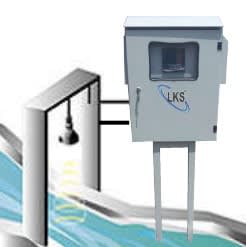
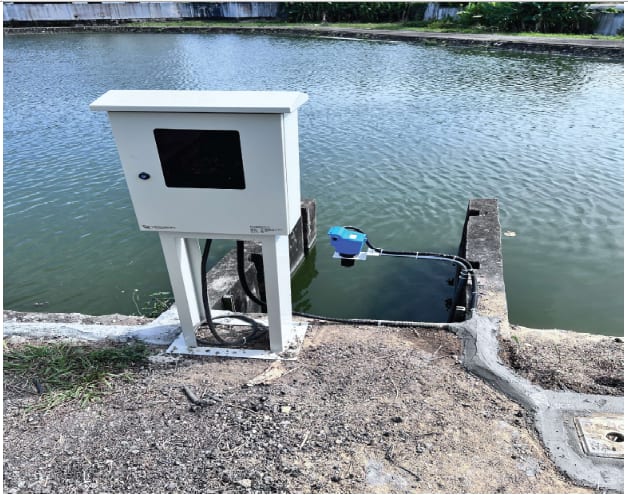
For automated measurement, LKS supplies the WF9000.V5 open-channel flow meter. Its ultrasonic sensor measures head over a primary device, and its controller can be configured for a Parshall flume and other structures. The display includes head height, flow and total flow. The product page lists accuracy as ±1% of full scale. That is a product specification, not a substitute for checking the installation, datum and selected flow relationship.
Keep the measurement chain clear in drawings and handover records. Identify the primary device, note where head is measured, record the zero reference and document which flow relationship is configured. Later checks are much easier when the displayed total can be traced back to its measurement basis.
Check that the flume suits the channel and flow range
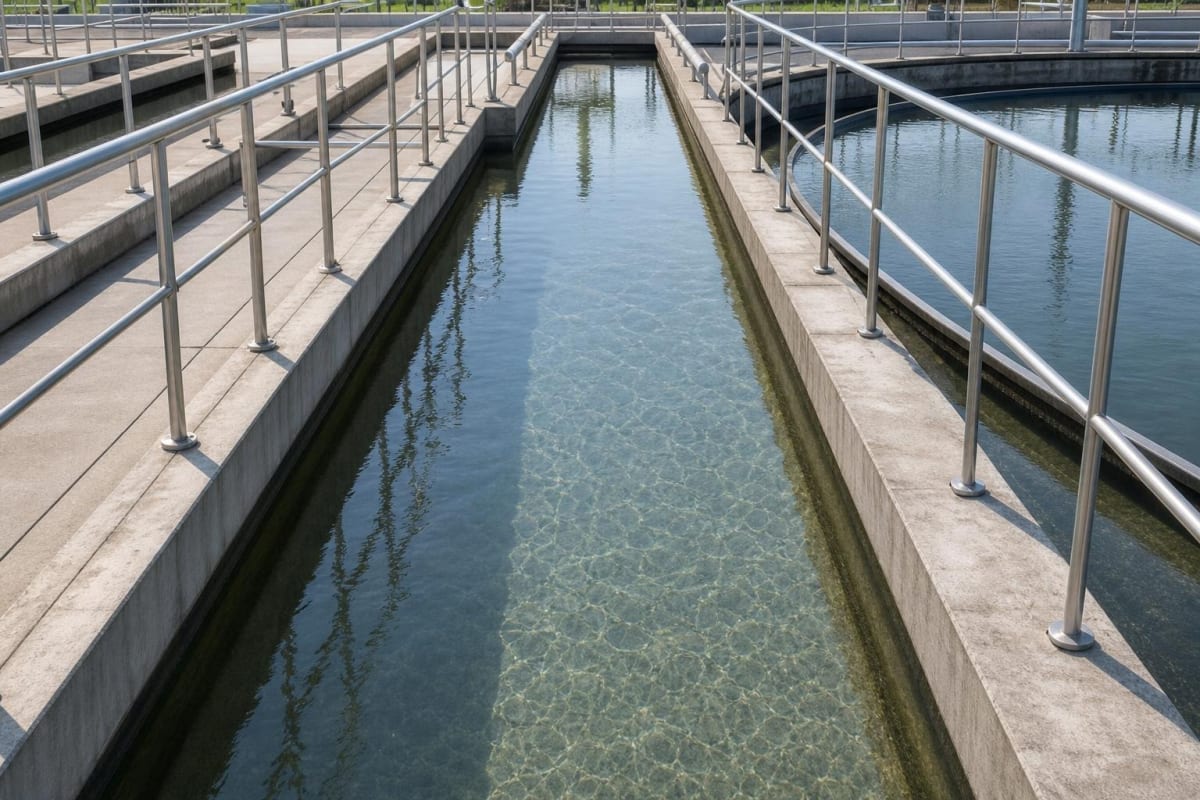
Before configuring the controller, identify the actual flume. Check the nameplate, as-built drawings or site records, then compare the recorded identity with the physical structure. Note the flume type and the dimensions needed to identify the appropriate head-to-flow relationship. Do not infer the flume size from a nearby controller label or assume an old configuration screen still matches the equipment in the channel.
Confirm that the controller uses the conversion for that specific primary device. A Parshall flume selection is not a generic setting for every flume, and a configuration for one geometry should not be carried over to another without verification. If the identity or dimensions are uncertain, resolve that uncertainty before using the displayed flow for process decisions or reporting.
Consider the expected operating range as part of the check. The instrument configuration needs to suit the installed flume and the intended measurement, including the selected units and any configured range. If the expected flow is outside the range for which the installed structure and configuration are suitable, the calculated value may not be useful. Check the flume documentation and controller settings together rather than assessing either in isolation.
The channel also affects the result. Look upstream for abrupt changes in shape, bends, obstructions or uneven inflow close to the flume. These may disturb the approach flow that the flume relationship assumes. Check the downstream discharge path too. A restriction or raised tailwater can change the hydraulic condition at the flume. The appropriate head-to-flow relationship depends on the installed structure and its approach conditions, so do not copy a rating or controller setup from another site simply because both locations have a Parshall flume.
If site records are incomplete, pause before changing the controller to make its reading look familiar. Confirm the geometry and obtain the applicable relationship for the actual flume. A setting should follow the primary device, not the other way round.
Choose the head-measurement position and reference
Use the prescribed head-measurement point for the installed flume geometry. For a Parshall flume, the upstream head point is in the converging section at a defined position relative to the throat. It is not safe to assume that the sensor belongs over the throat, at the outlet or wherever a mounting bracket happens to fit. The EPA guidance for inspecting Parshall flumes describes the measurement position in relation to the flume geometry. Confirm the exact point for the installed device rather than estimating it by eye.
Mount the sensor so its sensing path reaches the water surface at that point without being blocked by a support, cable, cover or other obstruction. Check that the mounting is secure and aligned as intended. A bracket that shifts can change the measured head even if the sensor continues to operate normally. Avoid positions where splashing, a disturbed surface or material collecting below the sensor makes the level unrepresentative.
Next, establish the zero reference. The instrument reference must correspond to the datum prescribed for the primary device. Do not assume the flume floor, channel invert or sensor face is automatically the correct zero. Consider the mounting height and the configured offset together. The EPA guidance on setting a primary-device gauge to its zero reference explains why an incorrect datum can introduce measurement error.
Record the reference used and how it was checked. If the sensor is replaced or its bracket is moved, verify the reference again instead of reusing the previous offset without inspection. A datum error changes the measured head. Because the controller derives flow from head rather than measuring discharge directly, the error can carry through to the calculated flow.
For a field comparison, take an independent level measurement at the prescribed point and use the same datum as the instrument. A comparison made at a different point, or against a different reference, will not show whether the installed sensor is correct. Make the checks close together in time if the level is changing, and record the conditions observed.
Inspect approach flow, level and downstream conditions
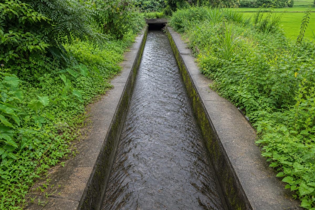
Before accepting a reading, inspect the water path. Look for sediment, grease, vegetation or debris that could change the flume shape or obstruct the channel. Accumulated material can alter the effective geometry even when the instrument display appears steady. Remove material only under the site's safe work procedures, then check the channel and surface again.
Check whether the flume is level and secure. Settlement, impact or uneven support can change the intended hydraulic profile. Look along the approach channel for skewed or uneven flow, visible turbulence, recirculation or an abrupt transition immediately upstream. These conditions can make the measured head less representative of the flow assumed by the relationship. Inspection guidance for flumes includes checks of approach flow, accumulated material, flume level and downstream restriction.
Then inspect the downstream water level and discharge path. If the outlet is restricted or water backs up against the flume, the structure may no longer be operating under the assumed free-discharge condition. A head-only conversion intended for one hydraulic condition may then give an unsuitable flow result. Do not try to correct a downstream hydraulic problem by changing the sensor zero. Find the cause and check the operating guidance for the actual flume.
Record what was observed: whether the channel was clean, whether the flume was level, and whether downstream water was affecting discharge. A flow value is more useful when its physical context is known. If conditions change with the plant operating state, inspect under representative conditions rather than relying on a single observation made when flow is quiet.
Configure the controller and verify the reading
Select the correct primary-device type in the controller and enter the flume information required by that instrument. Confirm that the displayed units and configured range suit the site's use. Check the selected structure and values against the flume identity and its documentation, not just against settings left by a previous operator.
The LKS WF9000.V5 is a programmable flume flow meter for Parshall flumes and other primary devices. It displays head, flow and total flow, and includes logging with USB data download. Optional RS485 Modbus communication is listed on the product page. These functions support monitoring and record keeping, but do not verify the hydraulic installation or the chosen conversion.
For a field check, compare the displayed head with an independent measurement made at the prescribed point and referenced to the same datum. If the two values disagree, inspect the sensor position, surface condition, mounting and zero reference before changing a setting. Also confirm that both measurements were made while the water level was sufficiently steady for a meaningful comparison.
If the head values agree but the flow seems implausible, check the device selection, flume information and applicable rating relationship. Revisit the approach and downstream conditions as well. Record the independent head, displayed head and flow, controller configuration and observed hydraulic condition. This evidence helps distinguish a sensing problem from a configuration error or a change in the flume's hydraulic conditions.
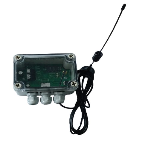
For remote viewing, the Cloud Monitoring System CLOUD 4.0 accepts isolated analogue inputs, including 4–20 mA signals, and supports cloud history reports and remote viewing. Confirm signal compatibility and the actual output arrangement before planning integration. Remote access makes data easier to review, but it cannot verify the flume datum or identify debris without a site inspection. LKS flow measurement and remote monitoring systems can form part of a wider monitoring arrangement.
Field checklist before handover and during routine checks
Use a repeatable checklist at commissioning and during maintenance. First, confirm the flume identity and dimensions against site records. Inspect that the structure is secure, level and free of material that could change the flow path. Check that the approach is not visibly disturbed and that downstream water is not restricting discharge.
Next, verify the sensor location against the prescribed measurement point. Check for an unobstructed sensing path and stable mounting. Confirm that the zero reference is tied to the primary device, and record how it was checked. Review the controller's primary-device selection, required flume information, units and configured range. Keep a record of the configuration so a later change can be identified.
Finally, compare the displayed head with an independent field measurement at the same point and datum. Use the applicable flume relationship or table to assess whether the calculated flow is plausible. Record both readings and the conditions observed. If the value feeds into wider water and wastewater monitoring, preserve enough context for another engineer to understand how it was produced.
Repeat the checks after work on the channel, flume, sensor bracket or controller configuration. Investigate a sudden change in head or flow when the operating conditions have not changed. The aim is not to adjust the instrument until the number looks familiar. Find which part of the measurement chain has changed, then address that cause.
Frequently asked questions
Where should head be measured in a Parshall flume?
Measure at the prescribed upstream point for the actual flume geometry. For a Parshall flume, the point is in the converging section at a defined position relative to the throat. Confirm its location from the flume documentation or applicable inspection guidance rather than assuming the throat is the measurement point.
Why can a correct level reading still produce an incorrect flow?
The level may be measured correctly while the controller uses the wrong flume type, geometry, units or head-to-flow relationship. A correct head reading also does not make a disturbed approach or restricted downstream condition valid for a relationship based on different hydraulic conditions.
How can downstream water affect flume readings?
A restricted outlet or high downstream water level can interfere with discharge and change the hydraulic behaviour assumed by the flow conversion. Check the outlet and downstream condition before treating a head-based calculated flow as reliable. Do not compensate for a hydraulic restriction by changing the sensor reference.
Can an ultrasonic sensor measure flow directly?
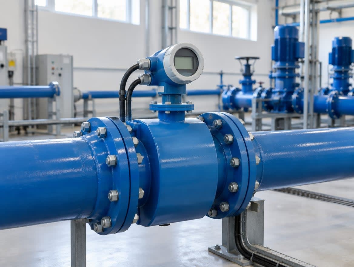
Not in this arrangement. The ultrasonic sensor measures water level or head above the primary device. The controller derives flow using the configured relationship for the flume. That differs from closed-pipe measurement, such as electromagnetic flow measurement, which uses a different measurement principle.
Reliable readings depend on a matched flume and conversion, a correctly positioned and referenced head measurement, and hydraulic conditions that suit the flume relationship. For help checking an open-channel measurement arrangement or selecting monitoring equipment, contact our engineers.

LKS Engineering TeamEngineers at LKS Group, supplying and servicing instrumentation, valves and monitoring systems in Malaysia since 1998.